ReyLight Pineapple Copper 519A sm353 dedomed emitter swap

ReyLight Pineapple Copper 519A sm353 dedomed emitter swap#
A torch enthusiast in Australia asked if I could swap a dedomed Nichia 519A sm353 3500K emitter into their ReyLight Pineapple Copper.
I asked Rey, the man behind ReyLight, if removing the MCPCB would be difficult due to thermal compound. Rey kindly replied and assured me that it is easier to remove compared to the MCPCB in the Pineapple Mini.
I have swapped the emitter in my own Pineapple Mini so I agreed to swapping one in the Pineapple.
Parts used#
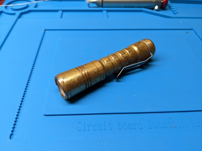
- ReyLight Pineapple Copper
- Nichia 519A sm353 3500K from Convoy
- Leaded Solder Paste
- Solder
- Thermal paste
Tools used#
- Soldering iron
- Solder wick
- UYUE 946-1010 hot plate
- Isopropyl alcohol
- Tweezers
- Hooks
- Feather razor blade
- Q-tips
- Paper towel
- Digital Multimeter
- PanaVise PAN201
Steps#
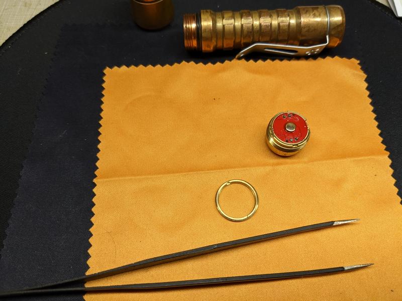
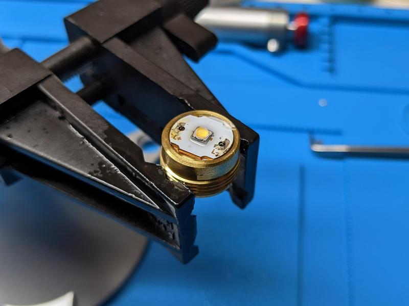
1. Unscrew the brass retaining ring in the head with tweezers. And then unscrew the pill with tweezers. There are two holes in the driver that can be used to rotate the pill. A little bit of force is required to ensure that the driver remains pressed against the pill while unscrewing it otherwise the driver might fall out and you could twist and damage the wires.
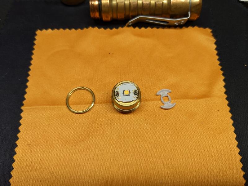
2. Remove the gasket from around the emitter. I left the reflector in the head to try to avoid getting any dust between the reflector and the glass lens.

3. Desolder the wires for the driver with solder wick and a soldering iron.
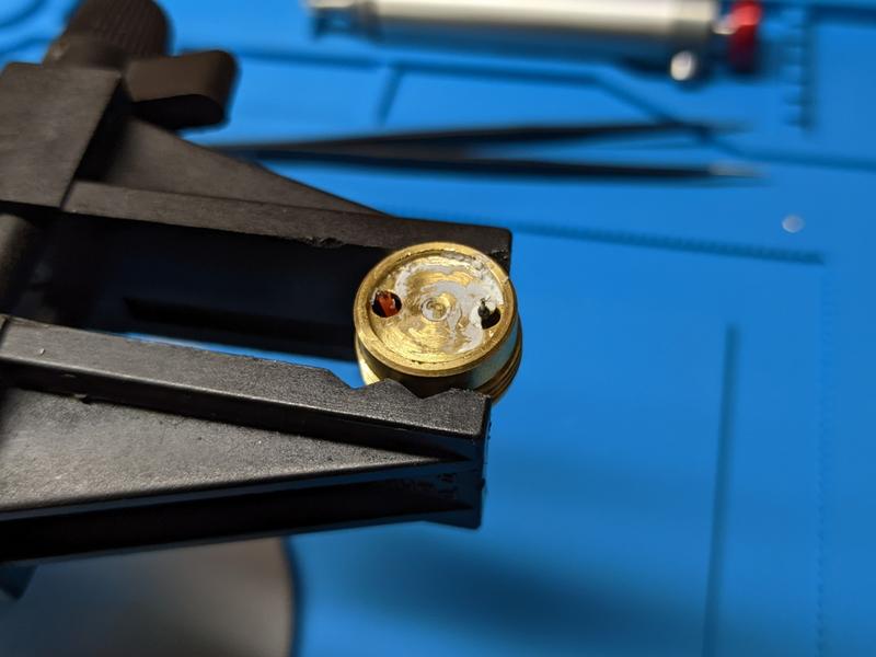
4. Spray the MCPCB and the shelf of the pill with isopropyl alcohol so that it loosens the thermal compound. Use small hooks or a small flat screwdriver to carefully remove the thermal compound. Pry the MCPCB up carefully by repeating a prying motion. It should gradually break the thermal compound under the MCPCB. Do not use too much force or you may bend or damage the MCPCB.
5. Remove the MCPCB from the head.
6. Clean thermal compound off the shelf of the head and the MCPCB using isopropyl alcohol and q-tips.
7. Place the MCPCB on a hot plate and heat up to 210 C.
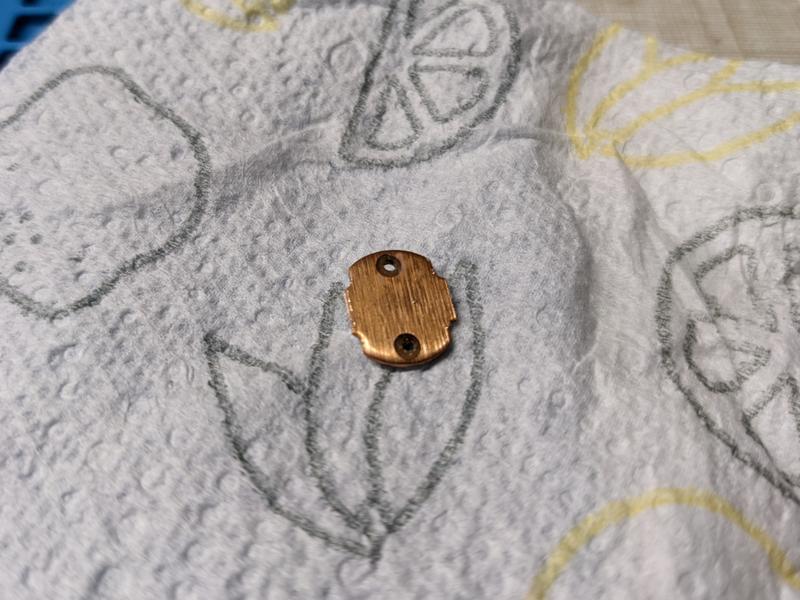
8. Remove the emitter with tweezers.
9. Take the MCPCB off the hot plate and add solder paste to the pads.
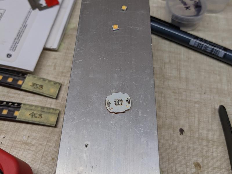
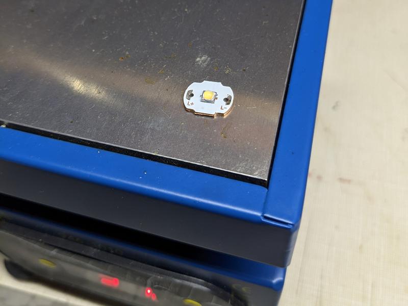
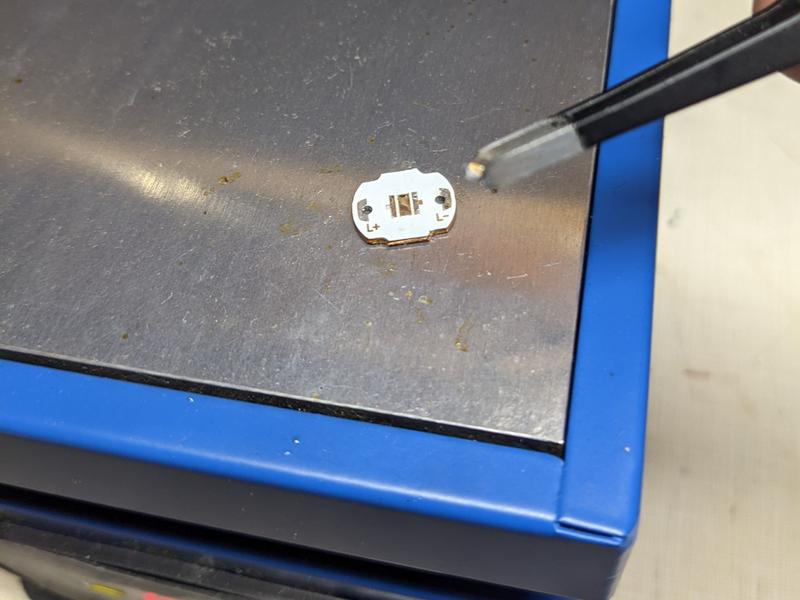
10. Place a Nichia 519A sm353 emitter on the pads with the dot in the corner oriented toward the negative side of the MCPCB.
11. Place the MCPCB on a hot plate and heat up to 210 C. Take the MCPCB off and place it on a heat resistant surface. Tap the emitter with tweezer handles to make the emitter squeeze excess solder out to the sides. The emitter should bounce back into the centre of the pads. Once cool, remove solder balls from around the side.
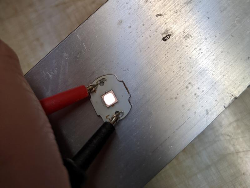
12. Test the emitter by connecting probes from a digital multimeter to the MCPCB’s anode and cathode while in diode test mode. The emitter should light up.
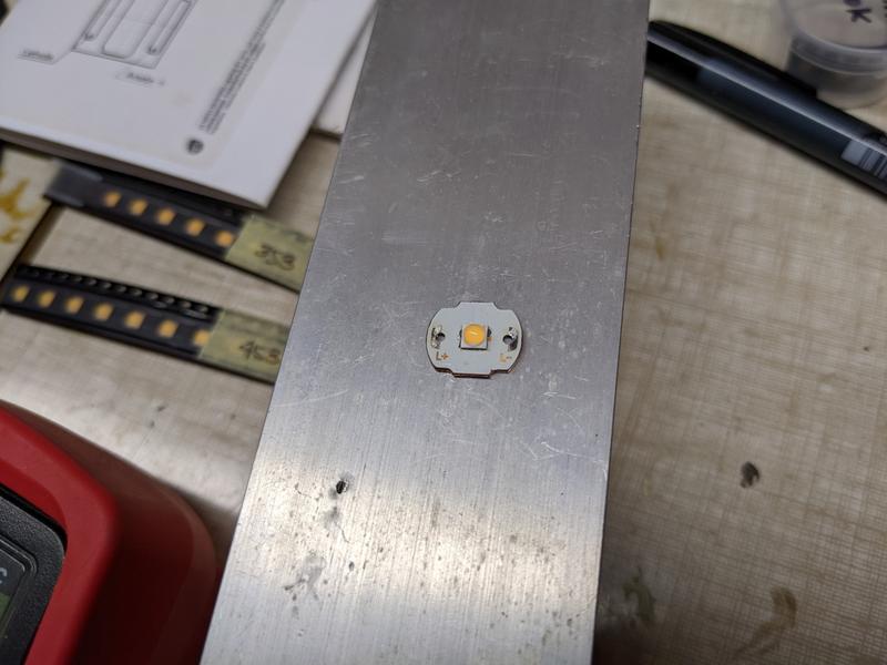
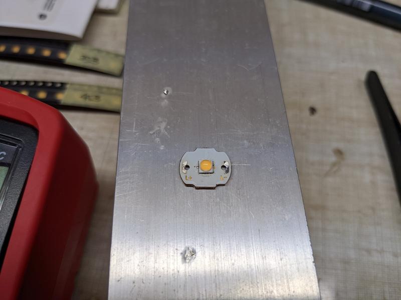
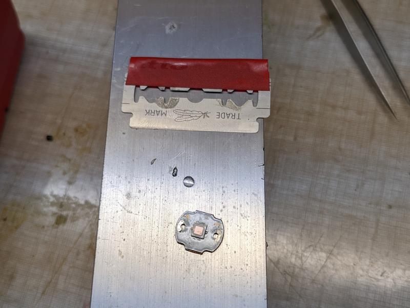
13. Remove the dome of the emitter by pinching it with your fingernails. There is a glass lens under the dome that must remain on. Carefully clean excess dome off by using a razor blade. You only want to remove the dome from above the square glass lens sitting on top of the phosphor so that the beam does not have any marks.
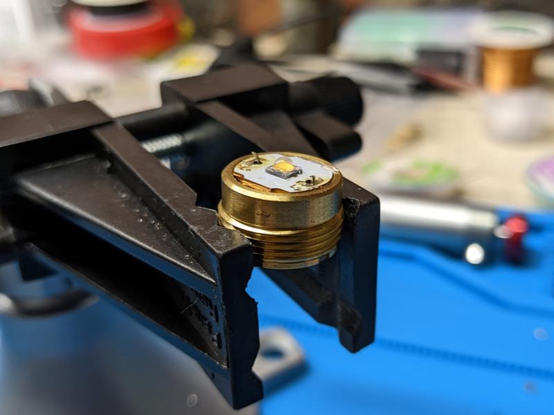
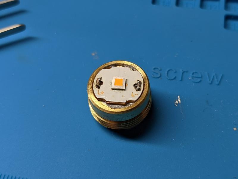
14. Add thermal paste the shelf of the pill and to the back of the MCPCB. Place the MCPCB back in the pill. Solder the wires onto the MCPCB. I did this step on a mat because the driver kept falling out.
15. Add the gasket around the emitter.
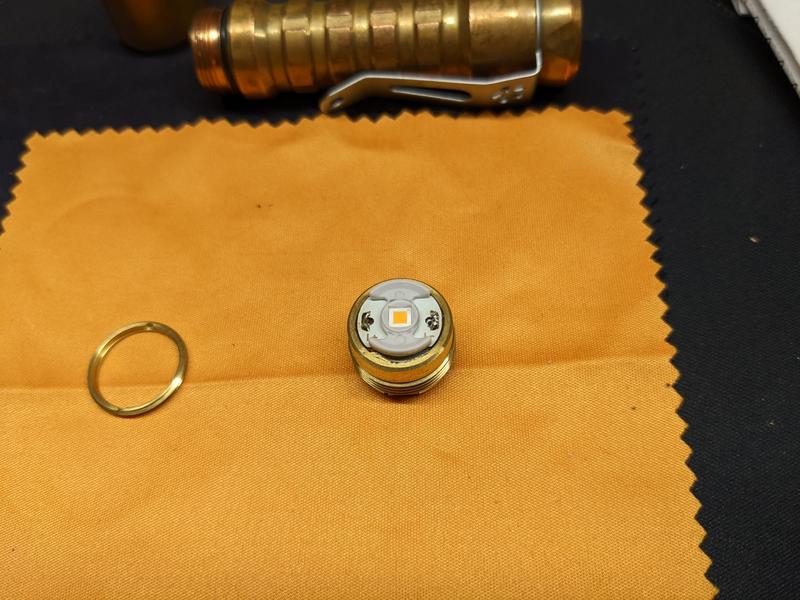
16. Carefully screw the pill back into the head using tweezers. Line up the gasket with the reflector so that it connects properly when tightening the pill. Screw the brass retaining ring back into the head to hold the driver securely in place.
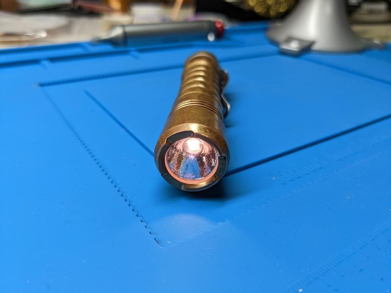
And the emitter swap is done!
CCT, CRI, duv#
I have taken Correlated Colour Temperature (CCT) and Colour Rendering Index (CRI, RA of R1-R8) measurements with the torch positioned half a metre away from an Opple Light Master Pro III (G3).
The CCT dropped from the rated 3500K to about 2700K after the dome was removed.
CRI is about 97.
The Delta u, v is negative. The beam is rosy and warm.
| Mode | CCT (K) | CRI (Ra) | x | y | Duv |
|---|---|---|---|---|---|
| ML | 2630 | 96.7 | 0.4591 | 0.4013 | -0.0034 |
| 2% | 2693 | 97.0 | 0.4547 | 0.4011 | -0.0031 |
| 20% | 2831 | 97.3 | 0.4457 | 0.4009 | -0.0023 |
| 100% | 2701 | 97.6 | 0.4520 | 0.3973 | -0.0043 |
Calculate Duv from CIE 1931 xy coordinates