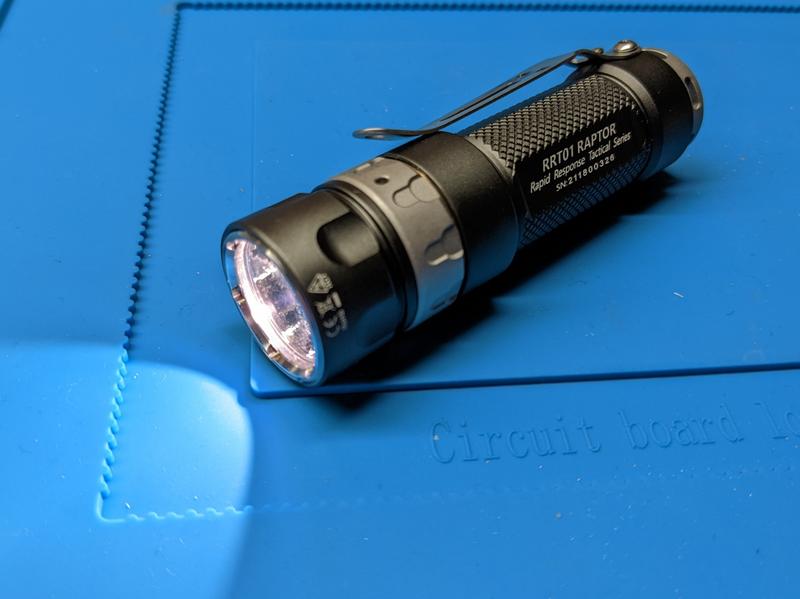
JETBeam RRT01 519A sm573 dedomed emitter swap

JETBeam RRT01 519A sm573 dedomed emitter swap#
Here is a photo tutorial of swapping and dedoming a Nichia 519A sm573 5700K emitter into a JETBeam RRT01.
I finally dedomed a 519A emitter. Fans of 519A emitters were right! The beam looks much nicer with the dome removed.
Cheule created an excellent video tutorial: “Flashlights 101: Emitter Swapping a Flashlight”. I found it extremely helpful in terms of figuring out how to open up an RRT01 without damaging it.
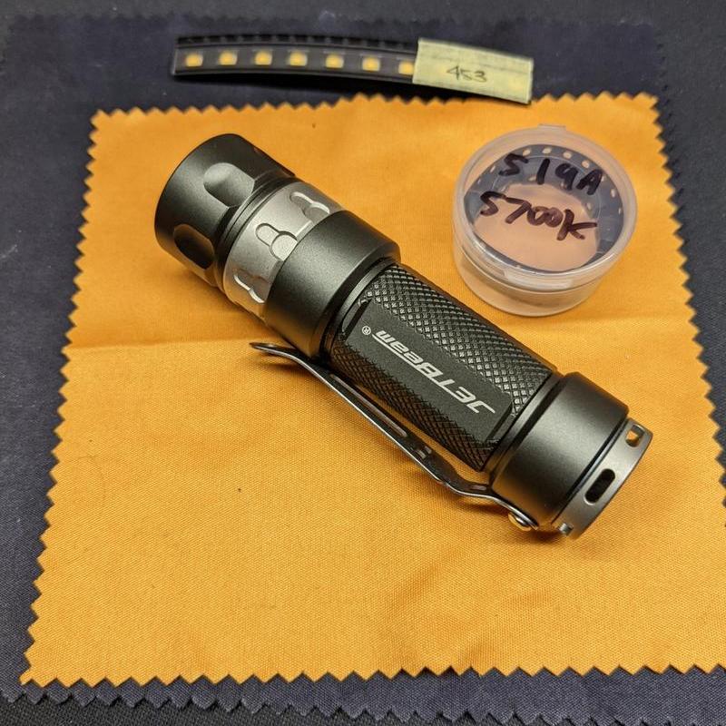
Parts used#
- JETBeam RRT01
- Nichia 519A sm573 5700K from Convoy
- Leaded Solder Paste
- Solder
- Thermal paste
Tools used#
- Circlip Pliers
- Soldering iron
- UYUE 946-1010 hot plate
- Isopropyl alcohol
- Tweezers
- Feather razor blade
- Q-tips
- Paper towel
- Digital Multimeter
- PanaVise PAN201
Steps#
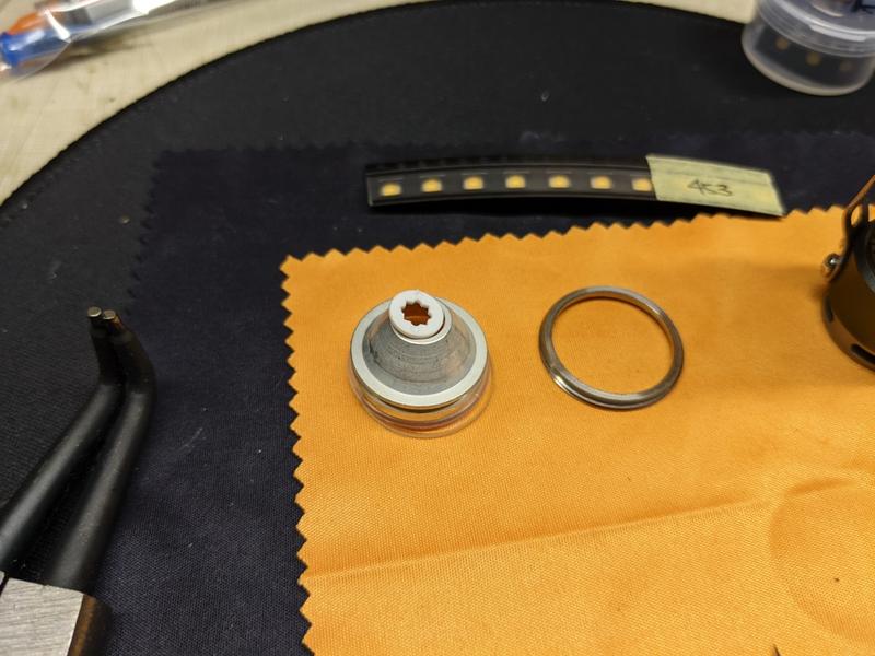
1. Unscrew the bezel with circlip pliers.
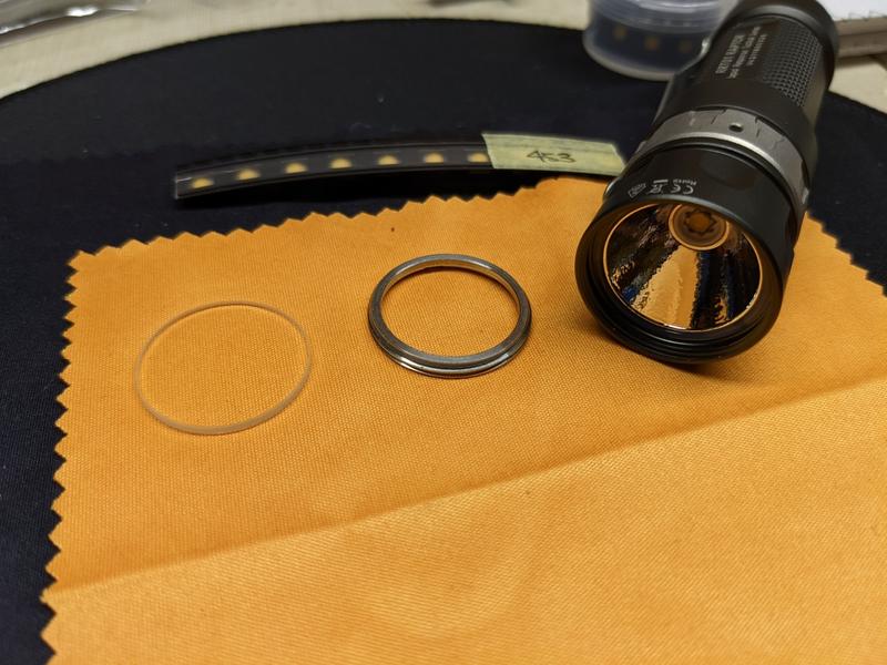
2. Dump the glass lens, o-ring, reflector and gasket out of the head.
3. Remove the screws from the MCPCB.
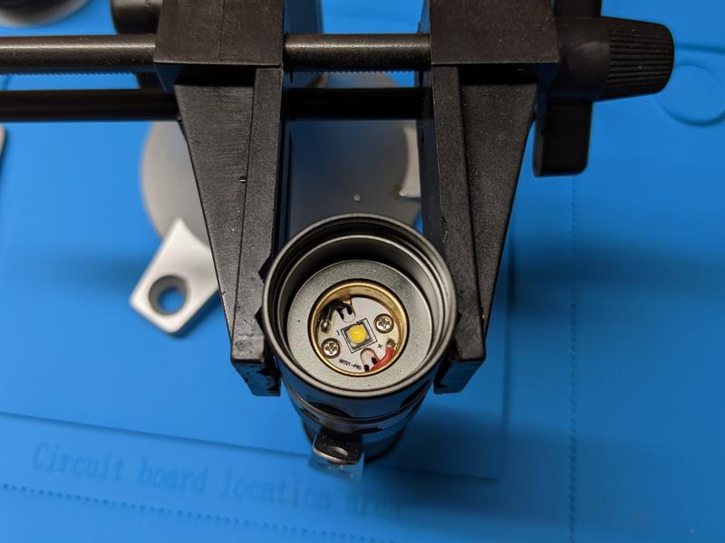
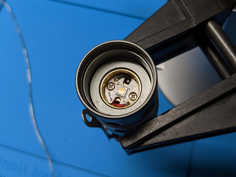
4. Desolder the wires from the MCPCB.
5. Remove the MCPCB from the head.
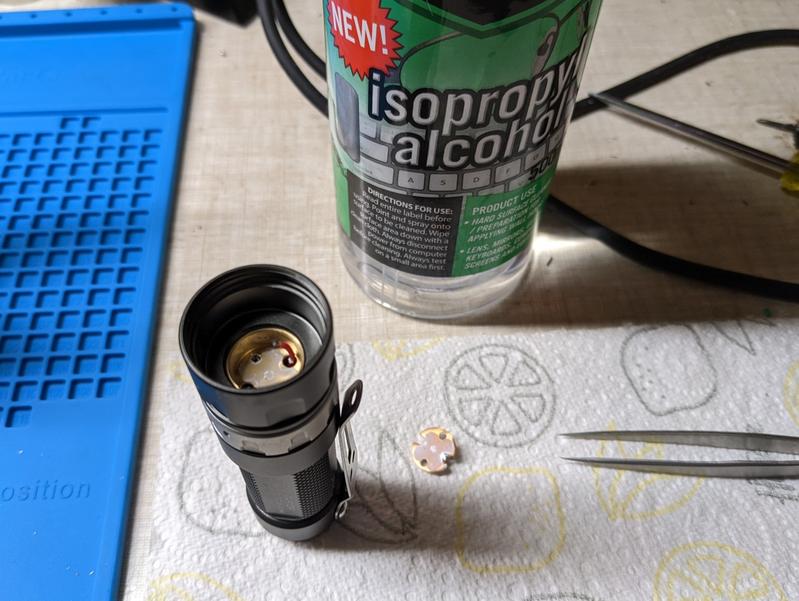
6. Clean thermal paste off the shelf of the head and the MCPCB using isopropyl alcohol.
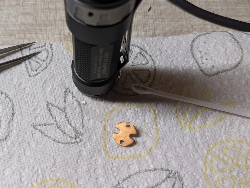
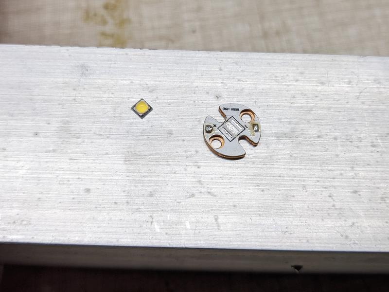
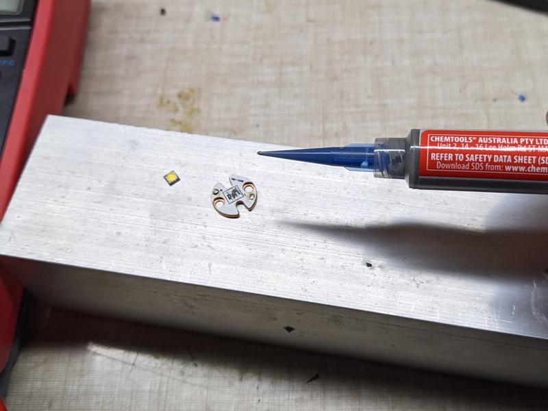
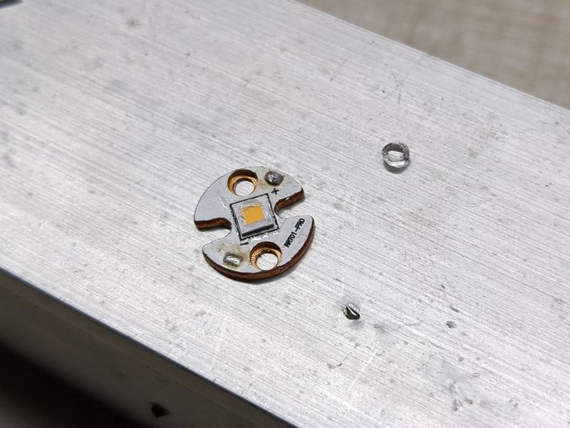
7. Place the MCPCB on a hot plate and heat up to 210 C. Remove the emitter with tweezers.
8. Take the MCPCB off the hot plate.
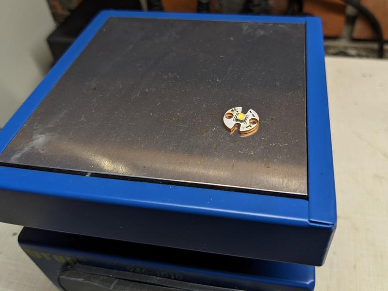
9. Add solder paste to the pads.
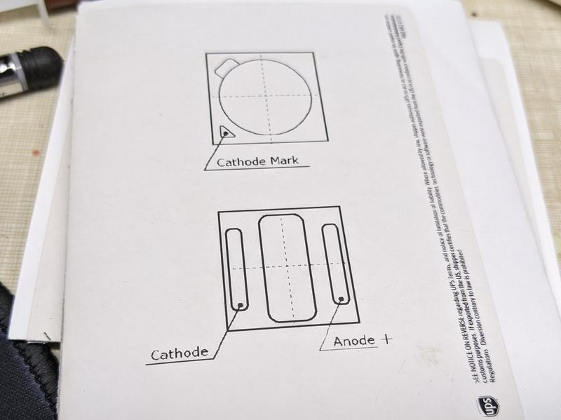
10. Place a Nichia 519A sm573 emitter on the pads with the dot in the corner oriented toward the negative side of the MCPCB.
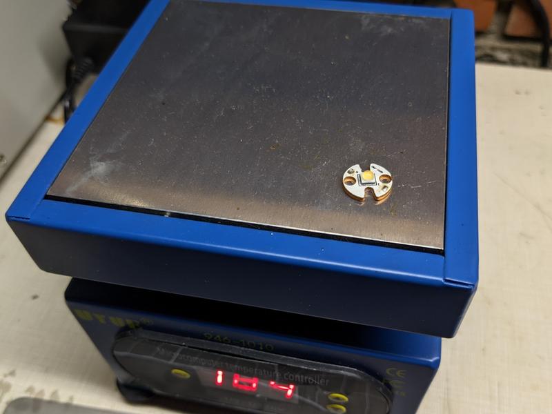
11. Place the MCPCB on a hot plate and heat up to 210 C. Take the MCPCB off and place it on a heat resistant surface. Tap the emitter with tweezer handles to make the emitter squeeze excess solder out to the sides. The emitter should bounce back into the centre of the pads. Once cool, remove solder balls from around the side.
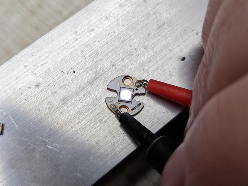
12. Test the emitter by connecting probes from a digital multimeter to the MCPCB’s anode and cathode while in diode test mode. The emitter should light up.
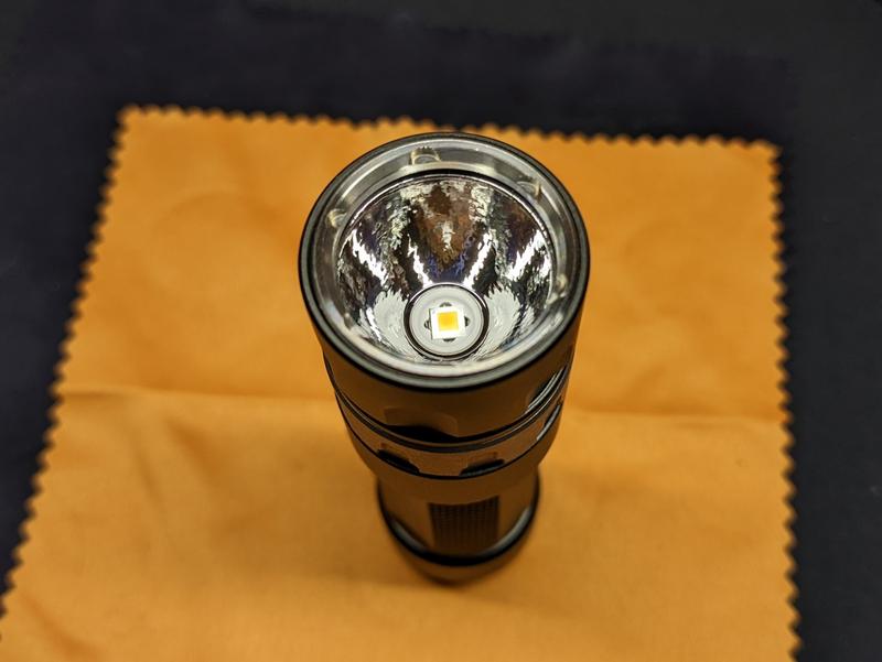
13. Remove the dome of the emitter by pinching it with your fingernails. There is a glass lens under the dome that must remain on.
14. Carefully clean excess dome off by using a razor blade. You only want to remove the dome from above the square glass lens sitting on top of the phosphor so that the beam does not have any marks.

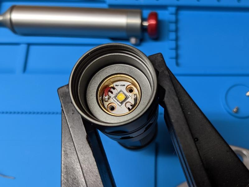
15. Add thermal paste the shelf of the head and to the back of the MCPCB.
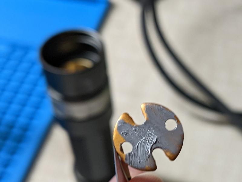
16. Place the MCPCB back in the head. Screw the MCPCB down to spread the thermal paste.
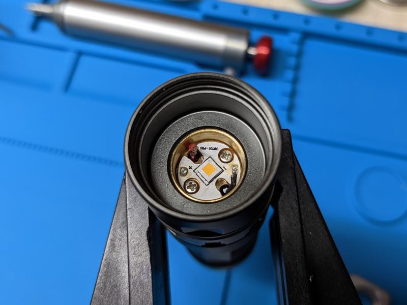
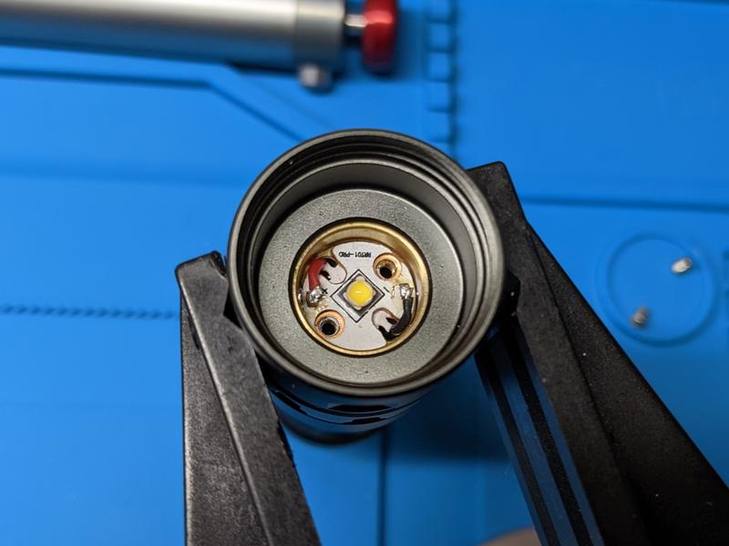
17. Solder the wires back onto the MCPCB.
13. Add the gasket around the emitter. Insert the bezel. Insert the o-ring. Insert the glass lens. Screw the bezel back on.
And the emitter swap is done!
CCT, CRI, duv#
I have taken Correlated Colour Temperature (CCT) and Colour Rendering Index (CRI, RA of R1-R8) measurements with the torch positioned half a metre away from an Opple Light Master Pro III (G3).
The CCT dropped from the rated 5700K to about 4000K after the dome was removed.
CRI is about 97.
The Delta u, v is slightly negative. The beam is a little bit rosy in theory but it looks neutral to my eyes.
| Mode | CCT (K) | CRI (Ra) | x | y | Duv |
|---|---|---|---|---|---|
| Low | 3872 | 97.5 | 0.3841 | 0.3715 | -0.0035 |
| Medium | 4040 | 97.6 | 0.3786 | 0.3740 | -0.0008 |
| High | 4144 | 96.8 | 0.3723 | 0.3628 | -0.0042 |
Calculate Duv from CIE 1931 xy coordinates
There is no Low, Medium or High with this rotary torch. I used these terms because it is easier then explaining how far I have rotated the ring. Low is a few levels above the absolute lowest moonlight. Medium is around the middle. And High is at the top of the ramp.
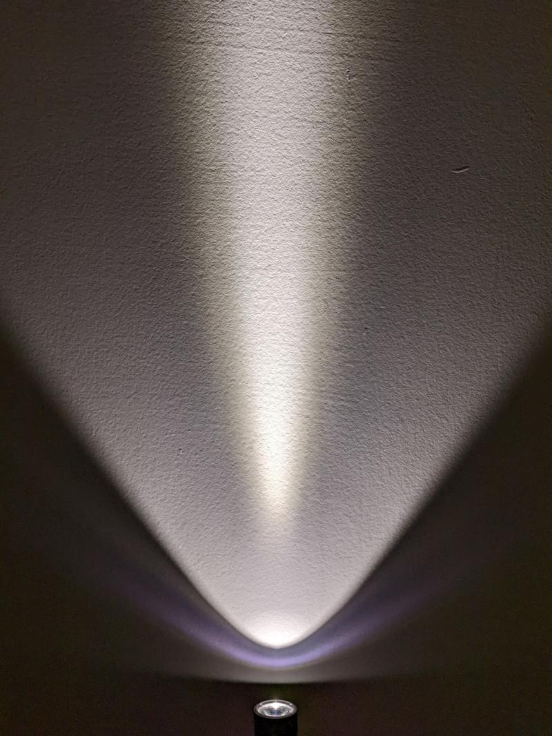
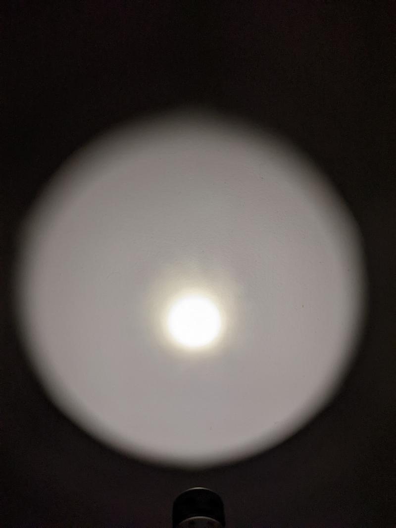
Beamshots#
Beamshots were taken with my phone without a fixed white balance.